Research, Testing and Development

Innovative Research, Testing and Development: Ensuring Superior Roofing and Cladding Quality
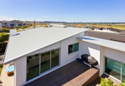
Modern house with sleek metal roofing and large glass windows overlooking a suburban neighborhood and open fields.

A Guarantee for High-Performance Roofing & Cladding

At The Roofing Store, we prioritize delivering the best roofing and cladding products through extensive research and development. Below is a structured overview of our testing processes and results.

Understanding the Impact of High Winds on CFS Roof Claddings

Cold-formed steel (CFS) roof claddings are subjected to significant suction and uplift pressures during high wind events. In regions with strong prevailing winds, such as New Zealand, these suction pressures are generated by turbulent wind flows around buildings. The intensity and location of these pressures vary both spatially and temporally.

Research has shown that the weakest link in a roofing system is often the connection between the roof sheeting and screw fasteners. When these connections fail, it can lead to the progressive loss of roofing materials. Fluctuating high wind suction pressures can cause two types of failure at the screw fastener connections: static pull-through failure or fatigue-related pull-through failure.

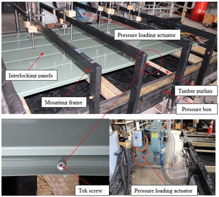
Pressure loading actuator and mounting frame setup with interlocking panels for testing wind pressure effects on roof cladding.
The testing apparatus includes a pressure loading actuator, mounting frame, and interlocking panels designed to simulate wind-induced suction forces on cold-formed steel claddings.
Finite element analysis (FEA) and experimental results comparing stress distribution and deformation of interlocking cladding sheets.
A comparative study of experimental and numerical results highlights the stress distribution and deformation in our interlocking cladding systems under wind loads.

Ensuring Compliance with Weather-Tightness Standards

In addition to wind load testing, we have performed weather-tightness testing of our cladding profiles in compliance with the New Zealand Building Code (E2/VM1). These tests ensure that our products meet the highest standards for resisting environmental elements, further enhancing their reliability in real-world applications.

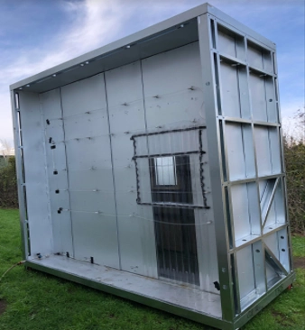
A full-scale test structure featuring steel cladding panels and a central window designed for real-world environmental testing.
The full-scale test structure incorporates steel cladding panels and a central window, replicating real-world conditions for environmental testing.
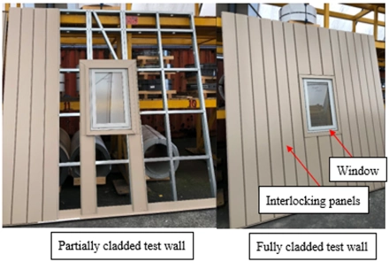
Partially and fully cladded test walls featuring interlocking panels and a central window for wind resistance evaluation.
The test walls show two configurations: a partially cladded wall and a fully cladded wall, each with interlocking panels and a central window for structural evaluation.
Pressure loading actuator and mounting frame setup with interlocking panels for testing wind pressure effects on roof cladding.
The testing apparatus includes a pressure loading actuator, mounting frame, and interlocking panels designed to simulate wind-induced suction forces on cold-formed steel claddings.

Comprehensive Testing for Performance Under Extreme Conditions

To address these challenges, our Research and Development team has conducted extensive studies. These include full-scale experiments and finite element modeling (FEA) of all TRS roofing and cladding profiles. The profiles were tested under static wind uplift and constant amplitude cyclic wind loading conditions to evaluate their performance and identify areas for improvement.

Finite element analysis (FEA) and experimental results comparing stress distribution and deformation of interlocking cladding sheets.
A comparative study of experimental and numerical results highlights the stress distribution and deformation in our interlocking cladding systems under wind loads.
Partially and fully cladded test walls featuring interlocking panels and a central window for wind resistance evaluation.
The test walls show two configurations: a partially cladded wall and a fully cladded wall, each with interlocking panels and a central window for structural evaluation.

Material Property Assessment and Precision Measurement

Before conducting wind and weather-tightness tests, we assessed the material properties of the steel using tensile coupon tests. To ensure precise modeling and accurate results, the initial geometric imperfections of the cladding profiles were measured using a 2D laser scanner. These measurements help us understand how imperfections influence overall performance.

Continuous Innovation for New Zealand’s Roofing Needs

Our ongoing research is dedicated to introducing new products and improving our existing range. By continuously refining our designs and testing methods, we aim to deliver roofing and cladding solutions that achieve the highest levels of quality and durability across New Zealand.

Material Property Evaluation: Ensuring Durability and Strength

Tensile Testing of KiwiColour Steel

To evaluate the material properties of KiwiColour® steel, tensile coupon tests were conducted on G300 and G550 grade steel coils. These tests adhered to the ISO 6892-1:2009(specifies the method for tensile testing of metallic materials and defines the mechanical properties which can be determined at room temperature.) standard, ensuring consistency and accuracy in material evaluation.

Sample Preparation and Testing Process

The tensile coupons were carefully prepared from the center of the cladding sheets used in testing. For each cladding profile, five coupons were taken from both the longitudinal and transverse directions. This approach provided a comprehensive understanding of the material’s behavior in different orientations.

The coupons were tested using an Instron 4469 tensile testing machine with a maximum load capacity of 50 kN. A calibrated extensometer, with a 50 mm gauge length, was used to measure the tensile strain of the coupons during the tests.

Stress-Strain Results

The results, including the test machine setup and the average stress-strain graphs for the steel, are shown in the figures below. These graphs provide crucial insights into the mechanical properties of the KiwiColour steel, ensuring its reliability for roofing and cladding applications.
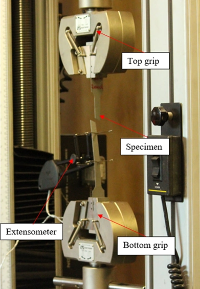
An Instron material testing machine with a mounted specimen, extensometer, top grip, and bottom grip for tensile testing.
The Instron machine is set up with a specimen clamped between the top and bottom grips, and an extensometer attached to measure deformation during tensile testing.

Precision Measurement of Initial Geometric Imperfections
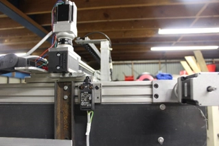
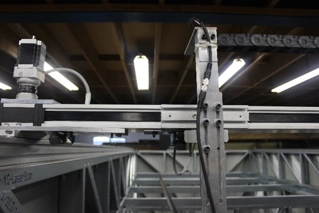
A stepper motor mounted on a linear guide rail for motion control in an industrial setup.

Laser Scanner Setup for Our Roofing and Cladding Profiles

To accurately measure the initial geometric imperfections in our roofing and cladding profiles, a laser scanner assembly was employed. The scanner setup is built on a robust steel frame measuring 5500 x 2500 x 1500 mm, as shown in the figure below. This frame supports a traveling platform mounted on precision rails for longitudinal motion along the 5500 mm direction.

Traveling Platform and Motion Control

The traveling platform is equipped with a stepper motor, which enables precise displacement-controlled motion through a rack and pinion system. For transverse motion (2500 mm direction), the platform includes a precision shaft that guides a movable laser scanner. This design ensures high accuracy and stability during the scanning process.

A laser scanner assembly mounted on a linear guide rail for high-precision measurement and data collection.
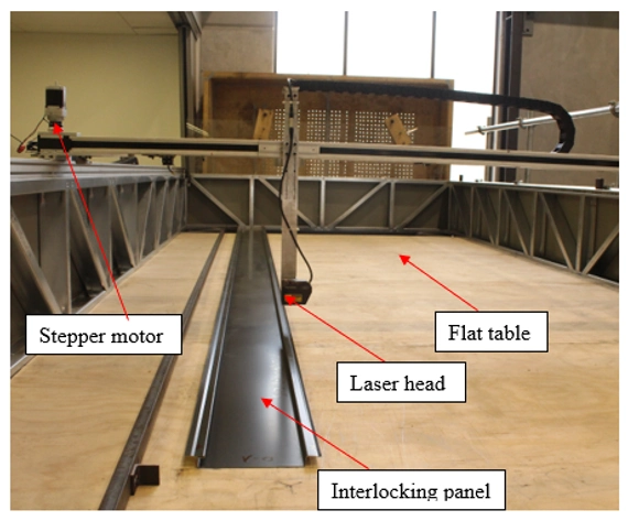
A laser scanning setup with a stepper motor, laser head, flat table, and interlocking panel for geometric analysis.

Laser Scanner Specifications and Data Collection

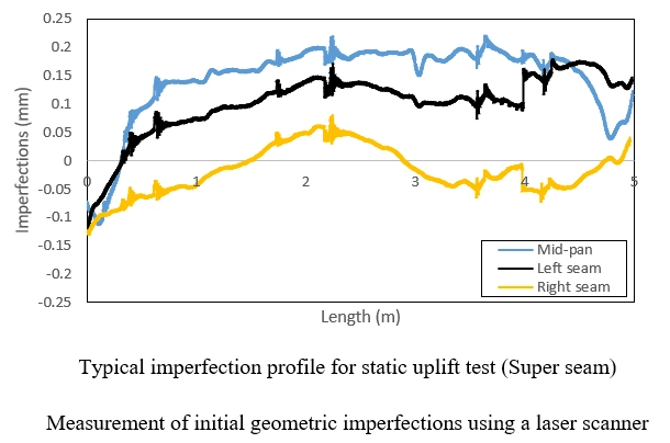
The laser scanner is capable of recording measurements with an impressive resolution of 0.0001 mm. A photograph of the setup for measuring geometric imperfections is shown below. Additionally, a typical plot of initial geometric imperfections versus length is provided. These detailed measurements were integral to the development of numerical models for each roofing and cladding profile.

Incorporation of Measurements in Numerical Models

The recorded imperfections were directly incorporated into the numerical models for our profiles. This step ensures that the simulations accurately reflect real-world conditions, enhancing the reliability and effectiveness of the models for performance analysis.

Graph showing the geometric imperfection profile for static uplift testing of a Super Seam, with data for mid-pan, left seam, and right seam.

Wind Load Testing: Ensuring the Resilience of Roofing and Cladding Profiles

Experimental Setup for Wind Load Testing

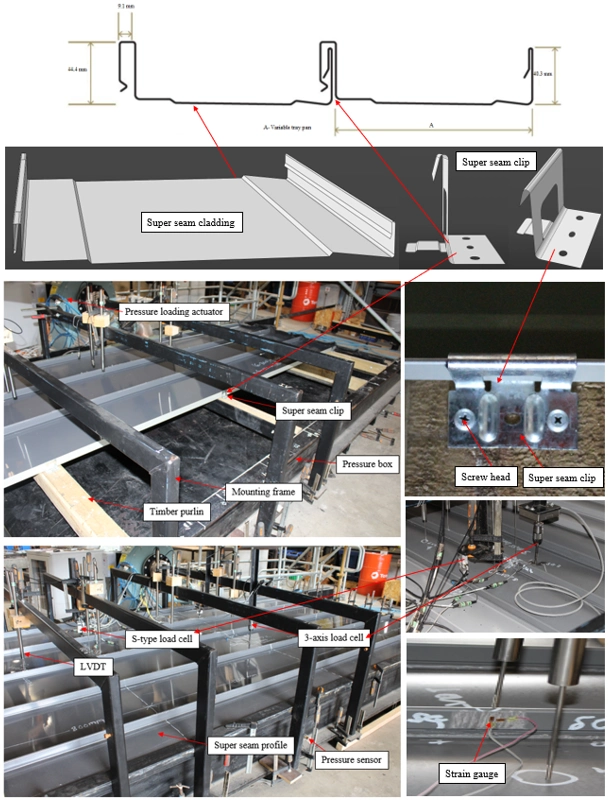
The Roofing Store profiles were subjected to static wind uplift and cyclic pressure tests within a rectangular pressure box. The experimental setup, shown in the figures below, includes a vacuum pump and a pressure loading actuator (PLA). These devices simulate wind uplift and cyclic pressure conditions inside the pressure box.

The tests aimed to evaluate the behavior of screws/clips under wind loading. Localized failure of screws/clips, followed by the global failure of the roofing or cladding assembly, was expected. These failures were controlled by load distribution across screws and clips at central and edge supports. To monitor performance, sensors were installed to measure deflection at the central support and mid-pan of the interlocking claddings. Four mounting frames held the sensors and load cells above the cladding panels, and three pressure sensors, each with a 20 kPa capacity, measured the uplift and cyclic pressure inside the box.

Each product was tested to the point of failure to determine its serviceability limit. The results provided valuable insights into the structural capacity and durability of TRS profiles. An experimental set up is shown below:
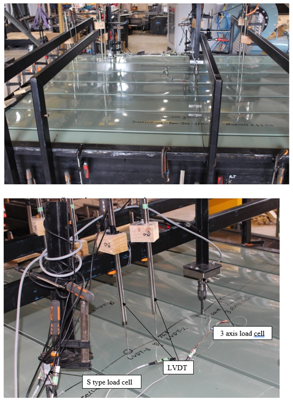
An experimental setup with a pressure box, interlocking panels, and sensors, including S-type load cells, 3-axis load cells, and LVDT, used for wind load testing on roofing systems.
Detailed diagram of the Super Seam Cladding test setup, including pressure box, mounting frames, sensors (S-type load cell, 3-axis load cell, LVDT), pressure loading actuator, and connection components like Super Seam Clip and screw head.

Static Uniform Uplift Pressure Testing

All specimens were tested under a uniform static uplift pressure. The pressure was applied at a constant rate until one of two scenarios occurred: failure of a screw/clip or global failure of the cladding assembly. Initially, the deflection of the cladding increased linearly with the applied pressure. However, as the pressure exceeded a certain threshold (dependent on the profile), the behavior became non-linear.

This non-linear response was observed through strain gauge readings taken near the critical screws/clips. The readings, captured both transversely and longitudinally, highlighted how the cladding deforms under increasing static wind uplift pressure.

Cyclic Pressure Testing

Cyclic pressure tests were conducted using sinusoidal loads, as illustrated in the figures below. The sinusoidal pressure was applied at a frequency of 1.2 Hz across all cladding profiles. The tests evaluated performance under varying peak cyclic loads, set at different percentages (100%, 80%, 70%, 60%, 50%, and 40%) of the measured static wind uplift capacity. The minimum cyclic load was approximately zero, maintaining consistency across tests.

These cyclic pressure tests adhered to the AS/NZS 1170.2 standard. By replicating real-world wind conditions, the results provided critical data on how TRS profiles withstand repeated loading over time, ensuring their reliability and durability under extreme conditions.

Conclusion

The combination of static and cyclic wind load testing allowed for a comprehensive evaluation of TRS roofing and cladding profiles. The data obtained will inform future design improvements, ensuring that the products continue to meet the highest standards of performance and safety under New Zealand’s demanding wind conditions.

Finite Element Modelling: Simulating Wind Loading on TRS Roofing and Cladding Profiles

01

Overview of Finite Element Modelling

To analyze the performance of TRS roofing and cladding profiles under static wind uplift pressure, nonlinear elastic-plastic finite element (FE) models were developed using the ABAQUS software (2017). The models were based on the centerline dimensions of the cladding profile cross-sections. Screw fasteners were simplified in the models, with only the screw head represented. Symmetry boundary conditions were applied to the free edge of adjacent claddings, and one intermediate span was modelled to reduce complexity and computational time.

02

Geometry and Material Properties

An elastic-plastic material model was implemented in the FE simulations. Material properties were derived from tensile coupon tests, ensuring accurate representation of the steel’s behavior. Following the ABAQUS guidelines, engineering material curves were converted into true material curves for precise modelling.

03

Element Types and Mesh Design

The finite elements chosen for the TRS claddings were S4R5 quadrilateral shell elements. These elements are shear-flexible and account for in-plane membrane and bending actions, enabling accurate modelling of longitudinal and transverse deformations. The screw heads were represented with three-dimensional eight-noded continuum elements.
A mesh size of 8 mm by 8 mm was used for the cladding profiles, validated through convergence studies. For the screw heads, a finer mesh size of 5 mm by 5 mm was applied. Mesh sensitivity analysis verified the accuracy of the element distribution across the cladding length and width.

04

Boundary Conditions and Load Application

Symmetry boundary conditions were applied along the longitudinal edges to replicate experimental conditions. Nodes along the symmetry plane were constrained against in-plane translations, while in-plane rotation was restricted at the longitudinal edges. The transverse edge near the end support was left free.
The screw head’s top layer nodes were constrained in all three translational directions, and master-slave contact pairs were defined between the screw head’s bottom face and the cladding profile’s top surface. Static wind uplift pressure was applied uniformly across all shell elements using the ABAQUS surface pressure load feature.

05

Analysis Methods

Elastic Buckling Analysis: Used to obtain eigenvectors for modelling initial geometric imperfections.

Nonlinear Static RIKS Analysis: Applied static wind uplift pressure to the claddings. The RIKS method was preferred for its ability to predict post-buckling behavior, providing a more comprehensive understanding of cladding performance compared to general static analysis.

06

Validation of the Finite Element Model

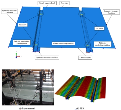
The finite element models were validated against experimental results for TRS cladding profiles under static wind uplift pressure. The FE analysis showed significant mid-pan deflections and accurately predicted failure modes and wind-load capacities. Strong correlations were observed between the experimental results and FE simulations, confirming the reliability and accuracy of the models.

This detailed finite element modelling approach ensures that TRS roofing and cladding profiles are rigorously tested and optimized for high-performance applications under extreme wind conditions.
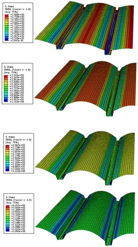
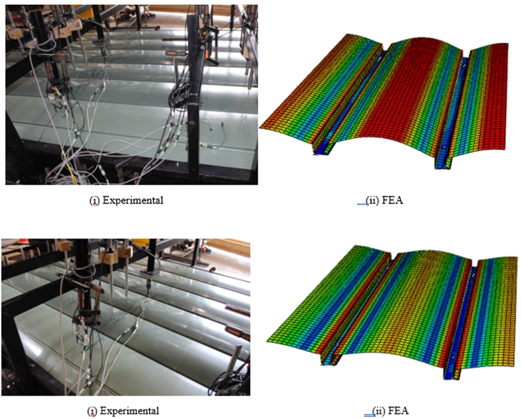
Finite element analysis (FEA) models showing stress distribution in TRS cladding profiles under increasing static wind uplift pressure.
Comparison of experimental setup and finite element analysis (FEA) models for TRS roofing and cladding profiles under static wind uplift loading.

Weather Tightness Testing: Ensuring Reliable Performance of TRS Interlocking Panels

Introduction to Weather Tightness Testing

The weather tightness testing of TRS interlocking panels was conducted in compliance with the New Zealand Building Code (E2/VM1). This work was generously supported by “NZ Government Funding for R&D – Callaghan Innovation”. The tests evaluated the panels’ ability to resist water penetration and maintain functionality under challenging conditions, following established guidelines for low-rise and medium-rise building facades.

Test Rig and Setup

The weather test rig used for this study measured 2.4 m x 3.6 m. Key features of the setup included:

  • Movement Joints: Vertical and horizontal joints were integrated into the test specimens.
  • Mounting and Sealing: The specimens were mounted and sealed into a simulated building frame using the same fixings intended for real-world construction.
  • Air Seal Continuity: The internal finishes and linings contributed to the air seal. This seal was extended from the sample to the test chamber.
  • Observation of Water Penetration: Transparent internal wall linings were used in parts of the test setup. These provided structural integrity while allowing clear observation of water infiltration.

To minimize external influences, framing members and interconnected joints were sealed at the specimen boundaries.
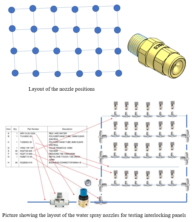
Layout of water spray nozzles and their positioning for testing interlocking panels, along with detailed nozzle and pipe components.
The layout of the water spray nozzles used for testing interlocking panels is shown, including a schematic of the nozzle positions and detailed components like pipes and connectors.
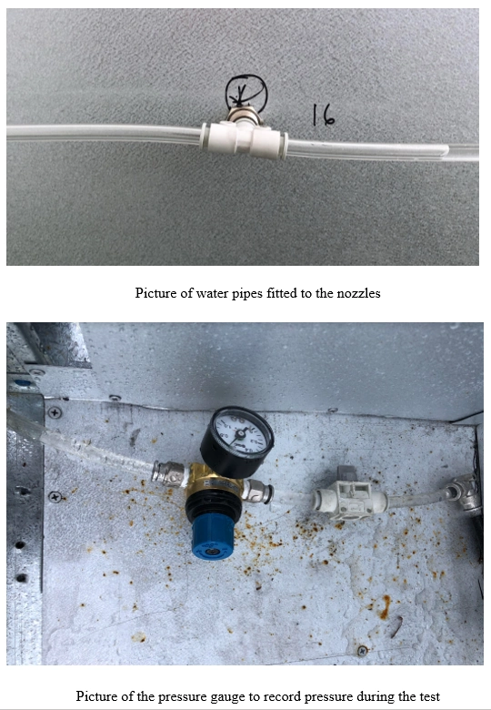
Water pipes connected to spray nozzles and a pressure gauge used to measure air pressure during testing.
Water pipes fitted to spray nozzles and a pressure gauge used to monitor pressure during weather-tightness testing of interlocking panels.

Testing Apparatus

The apparatus used for the experiments included the following components:

Manometer: Capable of measuring air pressure with ±2% accuracy. A fast-response manometer (response time ≤0.05s) was employed for cyclic water tests.

Chamber: An externally mounted chamber, sized to fit the test sample, was sealed to prevent air and water penetration around the edges.

Reversible Air Pump: Equipped with controls to apply pressurization and depressurization to the chamber.

Water Sprays: Simulated wind-driven rain conditions.

Airflow Measuring Devices: Calibrated orifice plates or laminar flow elements were used for accurate airflow measurement.

Experimental Testing

The E2/VM1 standard is specifically designed for testing the weather tightness of wall claddings on low-rise buildings. It is derived from AS/NZS 4284:2008(Sets out methods of testing building facades for environmental loading including water penetration and air infiltration as well as structural tests. Optional tests include seismic testing, seal degradation and building maintenance unit (BMU) restraint.), which originally built upon CSIRO’s work in Australia. While AS/NZS 4284:2008 assesses multiple facade aspects, E2/VM1 focuses solely on water penetration and management.

Key Testing Steps:

The test assessed the cladding’s ability to manage water within the cavity rather than allowing penetration into the building’s interior.

Static Water Penetration Tests:

These involved applying steady pressure while spraying the specimen with water.

Failure was noted when uncontrolled water penetration occurred on the interior surface.

Cyclic Pressure Testing:

Sinusoidal pressure was applied using a pressurized chamber.

The cyclic test followed specific steps outlined in AS/NZS 4284:2008, but with adjusted criteria to accommodate residential construction systems.

Wet Wall Test:

Defects were introduced to simulate failure of the primary sealing system.

Key Procedures

The tests were conducted at Kiwi Steel, under controlled conditions. Steps were performed as per design guidelines:

  1. Preconditioning:
    • Samples underwent preconditioning with positive and negative pressure (1515 Pa) applied for one minute each.
  2. Series 1: Static Pressure Water Penetration:
    • A maximum static pressure of 455 Pa was applied, following Clause 8.5 of AS/NZS 4284:2008.
  3. Series 2: Water Management Testing:
    • Tests were repeated in at least four critical locations:
      • Window/wall joints at three-quarters height of jambs.
      • Immediately above the head flashing.
      • At horizontal and vertical joints’ external seals.
      • Above any other wet wall penetration detail.

The introduction of controlled defects simulated the failure of primary weather defences. This allowed assessment of the cavity’s ability to manage water and prevent further penetration.

Conclusion

Weather tightness testing in compliance with E2/VM1 provided invaluable insights into the water resistance and management capabilities of TRS interlocking panels. The use of advanced testing methods ensures that these systems meet the highest standards, delivering reliable performance in low-rise and medium-rise buildings. These tests reaffirm TRS panels as a superior choice for New Zealand’s dynamic environmental conditions.

PEACE OF MIND

Confidence Backed by Research, Testing, and Development

At the core of our commitment to quality lies a robust foundation of research, testing, and development. Through rigorous experimentation and advanced engineering, we continuously refine our roofing and cladding solutions to meet and exceed industry standards.

It is this dedication to innovation and performance that gives us the confidence to offer up to 30 years of warranty on our steel roofing and cladding products. Whether it is weather-tightness testing, wind uplift resistance, or material durability assessments, every step of our process is designed to ensure long-lasting reliability and peace of mind for our customers.

Warranty of up to 30 years for The Roofing Store’s steel roofing and cladding products.
Ready to Work With Us?

Contact Us Today for Your Roofing and Cladding Solutions!

Let our experienced team provide you with reliable and high-quality steel roofing and cladding options tailored to your needs.

Scroll to Top