Research, Testing and Development
Innovative Research, Testing and Development: Ensuring Superior Roofing and Cladding Quality
Material Property Evaluation: Ensuring Durability and Strength
Tensile Testing of KiwiColour Steel
To evaluate the material properties of KiwiColour® steel, tensile coupon tests were conducted on G300 and G550 grade steel coils. These tests adhered to the ISO 6892-1:2009(specifies the method for tensile testing of metallic materials and defines the mechanical properties which can be determined at room temperature.) standard, ensuring consistency and accuracy in material evaluation.
Sample Preparation and Testing Process
The tensile coupons were carefully prepared from the center of the cladding sheets used in testing. For each cladding profile, five coupons were taken from both the longitudinal and transverse directions. This approach provided a comprehensive understanding of the material’s behavior in different orientations.
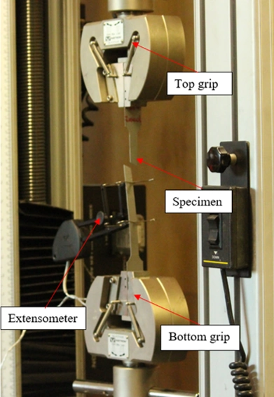
The coupons were tested using an Instron 4469 tensile testing machine with a maximum load capacity of 50 kN. A calibrated extensometer, with a 50 mm gauge length, was used to measure the tensile strain of the coupons during the tests.
Stress-Strain Results
The results, including the test machine setup and the average stress-strain graphs for the steel, are shown in the figures below. These graphs provide crucial insights into the mechanical properties of the KiwiColour steel, ensuring its reliability for roofing and cladding applications.
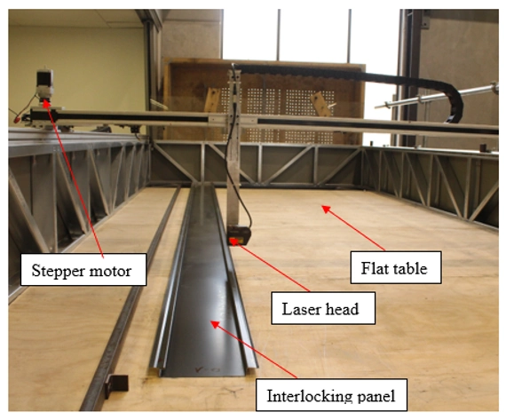
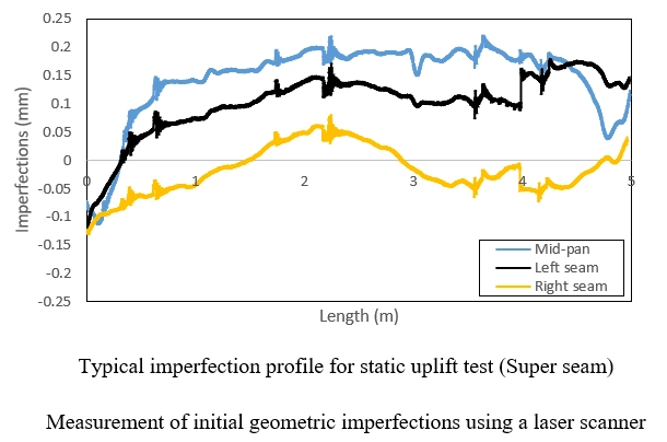
Precision Measurement of Initial Geometric Imperfections
Wind Load Testing: Ensuring the Resilience of Roofing and Cladding Profiles
Experimental Setup for Wind Load Testing
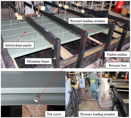
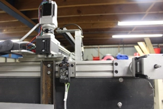
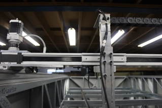
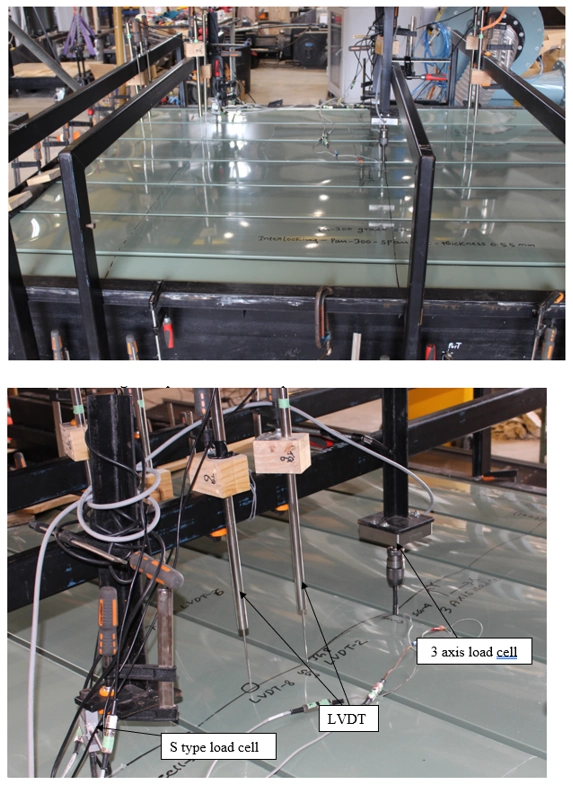
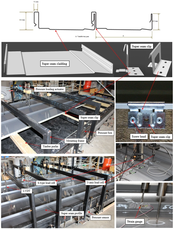
The Roofing Store profiles were subjected to static wind uplift and cyclic pressure tests within a rectangular pressure box. The experimental setup, shown in the figures below, includes a vacuum pump and a pressure loading actuator (PLA). These devices simulate wind uplift and cyclic pressure conditions inside the pressure box.
The tests aimed to evaluate the behavior of screws/clips under wind loading. Localized failure of screws/clips, followed by the global failure of the roofing or cladding assembly, was expected. These failures were controlled by load distribution across screws and clips at central and edge supports. To monitor performance, sensors were installed to measure deflection at the central support and mid-pan of the interlocking claddings. Four mounting frames held the sensors and load cells above the cladding panels, and three pressure sensors, each with a 20 kPa capacity, measured the uplift and cyclic pressure inside the box.
Each product was tested to the point of failure to determine its serviceability limit. The results provided valuable insights into the structural capacity and durability of TRS profiles. An experimental set up is shown below:
Static Uniform Uplift Pressure Testing
All specimens were tested under a uniform static uplift pressure. The pressure was applied at a constant rate until one of two scenarios occurred: failure of a screw/clip or global failure of the cladding assembly. Initially, the deflection of the cladding increased linearly with the applied pressure. However, as the pressure exceeded a certain threshold (dependent on the profile), the behavior became non-linear.
This non-linear response was observed through strain gauge readings taken near the critical screws/clips. The readings, captured both transversely and longitudinally, highlighted how the cladding deforms under increasing static wind uplift pressure.
Cyclic Pressure Testing
Cyclic pressure tests were conducted using sinusoidal loads, as illustrated in the figures below. The sinusoidal pressure was applied at a frequency of 1.2 Hz across all cladding profiles. The tests evaluated performance under varying peak cyclic loads, set at different percentages (100%, 80%, 70%, 60%, 50%, and 40%) of the measured static wind uplift capacity. The minimum cyclic load was approximately zero, maintaining consistency across tests.
These cyclic pressure tests adhered to the AS/NZS 1170.2 standard. By replicating real-world wind conditions, the results provided critical data on how TRS profiles withstand repeated loading over time, ensuring their reliability and durability under extreme conditions.
Conclusion
The combination of static and cyclic wind load testing allowed for a comprehensive evaluation of TRS roofing and cladding profiles. The data obtained will inform future design improvements, ensuring that the products continue to meet the highest standards of performance and safety under New Zealand’s demanding wind conditions.
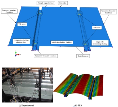
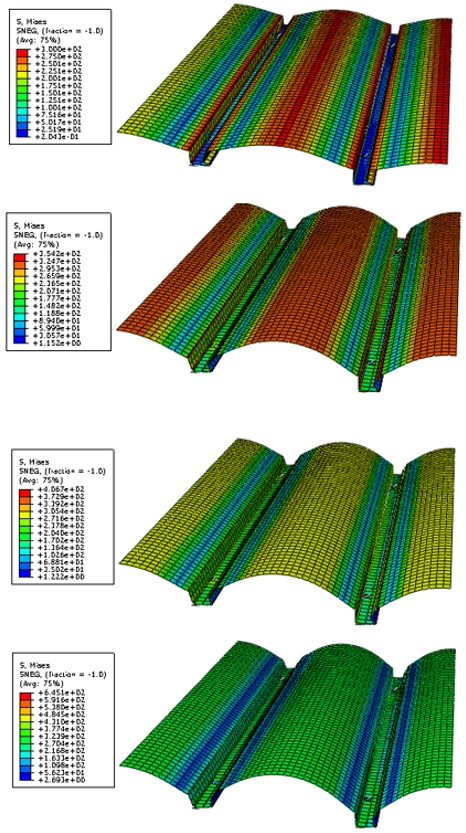
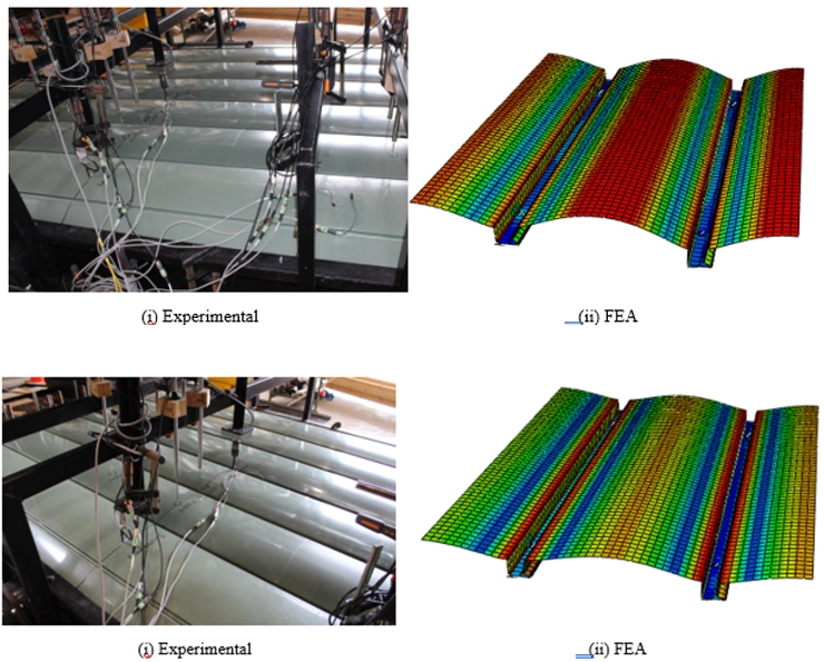
Finite Element Modelling: Simulating Wind Loading on TRS Roofing and Cladding Profiles
This detailed finite element modelling approach ensures that TRS roofing and cladding profiles are rigorously tested and optimized for high-performance applications under extreme wind conditions.
Weather Tightness Testing: Ensuring Reliable Performance of TRS Interlocking Panels
Introduction to Weather Tightness Testing
The weather tightness testing of TRS interlocking panels was conducted in compliance with the New Zealand Building Code (E2/VM1). This work was generously supported by “NZ Government Funding for R&D – Callaghan Innovation”. The tests evaluated the panels’ ability to resist water penetration and maintain functionality under challenging conditions, following established guidelines for low-rise and medium-rise building facades.
Test Rig and Setup
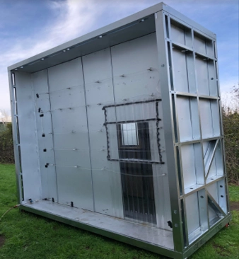
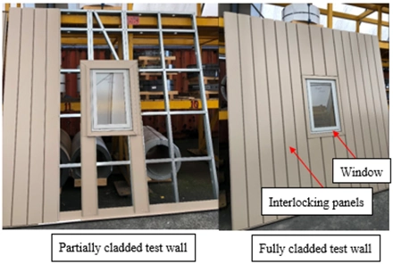
The weather test rig used for this study measured 2.4 m x 3.6 m. Key features of the setup included:
- Movement Joints: Vertical and horizontal joints were integrated into the test specimens.
- Mounting and Sealing: The specimens were mounted and sealed into a simulated building frame using the same fixings intended for real-world construction.
- Air Seal Continuity: The internal finishes and linings contributed to the air seal. This seal was extended from the sample to the test chamber.
- Observation of Water Penetration: Transparent internal wall linings were used in parts of the test setup. These provided structural integrity while allowing clear observation of water infiltration.
To minimize external influences, framing members and interconnected joints were sealed at the specimen boundaries.
Testing Apparatus
The apparatus used for the experiments included the following components:
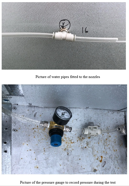
Manometer: Capable of measuring air pressure with ±2% accuracy. A fast-response manometer (response time ≤0.05s) was employed for cyclic water tests.
Chamber: An externally mounted chamber, sized to fit the test sample, was sealed to prevent air and water penetration around the edges.
Reversible Air Pump: Equipped with controls to apply pressurization and depressurization to the chamber.
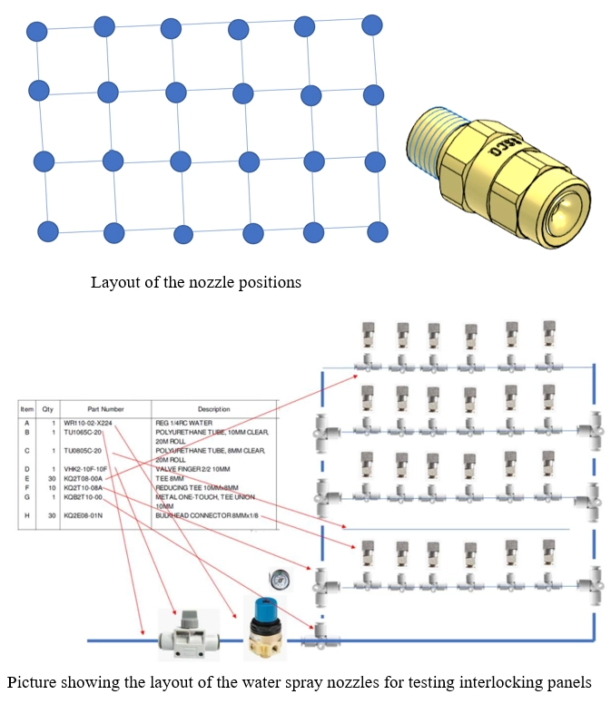
Water Sprays: Simulated wind-driven rain conditions.
Airflow Measuring Devices: Calibrated orifice plates or laminar flow elements were used for accurate airflow measurement.
Experimental Testing
The E2/VM1 standard is specifically designed for testing the weather tightness of wall claddings on low-rise buildings. It is derived from AS/NZS 4284:2008(Sets out methods of testing building facades for environmental loading including water penetration and air infiltration as well as structural tests. Optional tests include seismic testing, seal degradation and building maintenance unit (BMU) restraint.), which originally built upon CSIRO’s work in Australia. While AS/NZS 4284:2008 assesses multiple facade aspects, E2/VM1 focuses solely on water penetration and management.
Key Testing Steps:
The test assessed the cladding’s ability to manage water within the cavity rather than allowing penetration into the building’s interior.
Static Water Penetration Tests:
These involved applying steady pressure while spraying the specimen with water.
Failure was noted when uncontrolled water penetration occurred on the interior surface.
Cyclic Pressure Testing:
Sinusoidal pressure was applied using a pressurized chamber.
The cyclic test followed specific steps outlined in AS/NZS 4284:2008, but with adjusted criteria to accommodate residential construction systems.
Wet Wall Test:
Defects were introduced to simulate failure of the primary sealing system.
Key Procedures
The tests were conducted at Kiwi Steel, under controlled conditions. Steps were performed as per design guidelines:
- Preconditioning:
- Samples underwent preconditioning with positive and negative pressure (1515 Pa) applied for one minute each.
- Series 1: Static Pressure Water Penetration:
- A maximum static pressure of 455 Pa was applied, following Clause 8.5 of AS/NZS 4284:2008.
- Series 2: Water Management Testing:
- Tests were repeated in at least four critical locations:
- Window/wall joints at three-quarters height of jambs.
- Immediately above the head flashing.
- At horizontal and vertical joints’ external seals.
- Above any other wet wall penetration detail.
- Tests were repeated in at least four critical locations:
The introduction of controlled defects simulated the failure of primary weather defences. This allowed assessment of the cavity’s ability to manage water and prevent further penetration.
Conclusion
Weather tightness testing in compliance with E2/VM1 provided invaluable insights into the water resistance and management capabilities of TRS interlocking panels. The use of advanced testing methods ensures that these systems meet the highest standards, delivering reliable performance in low-rise and medium-rise buildings. These tests reaffirm TRS panels as a superior choice for New Zealand’s dynamic environmental conditions.

